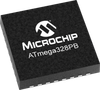
The high-performance, low-power Microchip 8-bit AVR® RISC-based microcontroller combines 64 KB ISP Flash memory with read-while-write capabilities, 2 KB EEPROM, 4 KB SRAM, 27 general purpose I/O lines, 32 general purpose working registers, two flexible timer/counters with compare modes and PWM, one UART with HW LIN, an 11-channel 10-bit A/D converter with two differential programmable gain input stages, a 10-bit D/A converter, a programmable watchdog timer with an internal individual oscillator, SPI serial port, an on-chip debug system, and four software selectable power saving modes. The device operates between 2.7-5.5 volts.
By executing powerful instructions in a single clock cycle, the device achieves throughputs approaching one MIPS per MHz, balancing power consumption and processing speed.
Additional Features
131 Powerful Instructions
Most Single Clock Cycle Execution
32 x 8 General Purpose Working Registers
Fully Static Operation
Up to 20 MIPS Throughput at 20 MHz
On-Chip 2-Cycle Multiplier
32 KB of In-System Self-Programmable Flash program memory
1 KB EEPROM
2 KB Internal SRAM
Write/Erase Cycles: 10,000 Flash/100,000 EEPROM
Data retention: 20 years at 85°C
In-System Programming by On-chip Boot Program
True Read-While-Write Operation
Programming Lock for Software Security
Capacitive Touch Buttons, Sliders and Wheels
24 Self-Cap Channels and 144 Mutual Cap Channels
Two 8-bit Timer/Counters with Separate Prescaler and Compare Mode
Three 16-bit Timer/Counters with Separate Prescaler, Compare Mode, and Capture Mode
Real Time Counter with Separate Oscillator
Ten PWM Channels
8-channel 10-bit ADC in TQFP and QFN/MLF package
Two Programmable Serial USARTs
Two Master/Slave SPI Serial Interfaces
Two Byte-Oriented Two-Wire Serial Interfaces (Philips I2C Compatible)
Programmable Watchdog Timer with Separate On-chip Oscillator
On-Chip Analog Comparator
Interrupt and Wake-Up on Pin Change
Power-On Reset and Programmable Brown-Out Detection
Internal 8 MHz Calibrated Oscillator
External and Internal Interrupt Sources
Six Sleep Modes: Idle, ADC Noise Reduction, Power-save, Power-down, Standby, and Extended Standby
Clock Failure Detection Mechanism and Switch to Internal 8 MHz RC Oscillator in case of Failure
Individual Serial Number to Represent a Unique ID
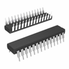
27 Programmable I/O Lines
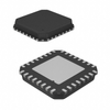
32-pin TQFP and 32-pin QFN/MLF
1.8-5.5V
-40°C to 105°C
0-4 MHz @ 1.8 - 5.5V
0-10 MHz @ 2.7 - 5.5.V
0-20 MHz @ 4.5 - 5.5V
Active Mode: 0.24 mA
Power-Down Mode: 0.2 μA
Power-Save Mode: 1.3 μA (Including 32 kHz RTC)
The high-performance, low-power Microchip 8-bit AVR® RISC-based microcontroller combines 64 KB ISP Flash memory with read-while-write capabilities, 2 KB EEPROM, 4 KB SRAM, 27 general purpose I/O lines, 32 general purpose working registers, two flexible timer/counters with compare modes and PWM, one UART with HW LIN, an 11-channel 10-bit A/D converter with two differential programmable gain input stages, a 10-bit D/A converter, a programmable watchdog timer with an internal individual oscillator, SPI serial port, an on-chip debug system, and four software selectable power saving modes. The device operates between 2.7-5.5 volts.
By executing powerful instructions in a single clock cycle, the device achieves throughputs approaching one MIPS per MHz, balancing power consumption and processing speed.
Additional Features
- 131 Powerful Instructions
- Most Single Clock Cycle Execution
- 32 x 8 General Purpose Working Registers
- Fully Static Operation
- Up to 20 MIPS Throughput at 20 MHz
- On-Chip 2-Cycle Multiplier
- 32 KB of In-System Self-Programmable Flash program memory
- 1 KB EEPROM
- 2 KB Internal SRAM
- Write/Erase Cycles: 10,000 Flash/100,000 EEPROM
- Data retention: 20 years at 85°C
- In-System Programming by On-chip Boot Program
- True Read-While-Write Operation
- Programming Lock for Software Security
- Capacitive Touch Buttons, Sliders and Wheels
- 24 Self-Cap Channels and 144 Mutual Cap Channels
- Two 8-bit Timer/Counters with Separate Prescaler and Compare Mode
- Three 16-bit Timer/Counters with Separate Prescaler, Compare Mode, and Capture Mode
- Real Time Counter with Separate Oscillator
- Ten PWM Channels
- 8-channel 10-bit ADC in TQFP and QFN/MLF package
- Two Programmable Serial USARTs
- Two Master/Slave SPI Serial Interfaces
- Two Byte-Oriented Two-Wire Serial Interfaces (Philips I2C Compatible)
- Programmable Watchdog Timer with Separate On-chip Oscillator
- On-Chip Analog Comparator
- Interrupt and Wake-Up on Pin Change
- Power-On Reset and Programmable Brown-Out Detection
- Internal 8 MHz Calibrated Oscillator
- External and Internal Interrupt Sources
- Six Sleep Modes: Idle, ADC Noise Reduction, Power-save, Power-down, Standby, and Extended Standby
- Clock Failure Detection Mechanism and Switch to Internal 8 MHz RC Oscillator in case of Failure
- Individual Serial Number to Represent a Unique ID
- 27 Programmable I/O Lines
- 32-pin TQFP and 32-pin QFN/MLF
- 1.8-5.5V
- -40°C to 105°C
- 0-4 MHz @ 1.8 - 5.5V
- 0-10 MHz @ 2.7 - 5.5.V
- 0-20 MHz @ 4.5 - 5.5V
- Active Mode: 0.24 mA
- Power-Down Mode: 0.2 μA
- Power-Save Mode: 1.3 μA (Including 32 kHz RTC)