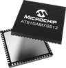
Microchip Technology, Inc. AT91SAM7S512

Description
Microchip's ARM®-based SAM7S512 is a member of the SAM7S series of flash microcontrollers based on the 32-bit ARM7TDMI RISC processor. It operates at a maximum speed of 55MHz and features 512KB of dual bank flash memory and 64KB of SRAM. The peripheral set includes a Full Speed USB device and PHY at 12Mbps, UART, two USARTs, TWI (I2C), SPI, SSC, two PWM timers, three 16-bit timers,RTT, 8x10-bit ADC and 32 IO lines. It achieves single-cycle instruction access from embedded flash at 27 MIPS. The multi-layer bus matrix, multiple SRAM banks, PDC, and DMA support parallel tasks and maximize data throughput. The SAM7S512 operates from 1.65V to 3.6V and is available in 64-pin LQFP and QFN packages. Additional Features Microcontroller Features Core ARM7TDMI® ARM® Thumb® Processor 32-bit RISC Architecture High-density 16-bit Instruction Set EmbeddedICE™ In-circuit Emulation, Debug Communication Channel Support Memories 512 Kbytes (SAM7S512) Organized in Two Contiguous Banks of 1024 Pages of 256 Bytes (Dual Plane) 64 Kbytes embedded SRAM, Single-cycle Access at Maximum Speed Memory Controller (MC) Memory Protection Unit System Embedded 1.8V Regulator, Drawing up to 100 mA for the Core and External Components Based on Power-on Reset Cells and Low-power Factory-calibrated Brownout Detector Low-power RC Oscillator, 3 to 20 MHz On-chip Oscillator and One PLL Power Management Controller (PMC) Advanced Interrupt Controller (AIC) Two-wire UART and Support for Debug Communication Channel interrupt, Programmable ICE Access Prevention 20-bit Programmable Counter plus 12-bit Interval Counter Windowed Watchdog (WDT) Real-time Timer (RTT) 32 Parallel Input/Output Controllers (PIO) Eleven Peripheral DMA Controller (PDC) Channels Four High-current Drive I/O lines, Up to 16 mA Each Package 64-lead LQFP 64-pad QFN Peripheral Features One Synchronous Serial Controller (SSC) Two Universal Synchronous/Asynchro nous Receiver Transmitters (USART) One Master/Slave Serial Peripheral Interfaces (SPI) One USB 2.0 Full Speed (12 Mbits per second) Device Port One Three-channel 16-bit Timer/Counter (TC) One Four-channel 16-bit PWM Controller (PWMC) One Two-wire Interface (TWI) Analog Features One 8-channel 10-bit Analog-to-Digital Converter, Four Channels Multiplexed with Digital I/Os Fully Static Operation Up to 55 MHz at 1.8V and 85⋅ C Worst Case Conditions Up to 48 MHz at 1.65V and 85⋅ C Worst Case Conditions Debugger Development Support SAM-BA - Interface with SAM-BA Graphic User Interface IEEE® 1149.1 JTAG Boundary Scan on All Digital Pins
Datasheet
Description
Microchip's ARM®-based SAM7S512 is a member of the SAM7S series of flash microcontrollers based on the 32-bit ARM7TDMI RISC processor. It operates at a maximum speed of 55MHz and features 512KB of dual bank flash memory and 64KB of SRAM. The peripheral set includes a Full Speed USB device and PHY at 12Mbps, UART, two USARTs, TWI (I2C), SPI, SSC, two PWM timers, three 16-bit timers,RTT, 8x10-bit ADC and 32 IO lines. It achieves single-cycle instruction access from embedded flash at 27 MIPS. The multi-layer bus matrix, multiple SRAM banks, PDC, and DMA support parallel tasks and maximize data throughput. The SAM7S512 operates from 1.65V to 3.6V and is available in 64-pin LQFP and QFN packages. Additional Features Microcontroller Features Core ARM7TDMI® ARM® Thumb® Processor 32-bit RISC Architecture High-density 16-bit Instruction Set EmbeddedICE™ In-circuit Emulation, Debug Communication Channel Support Memories 512 Kbytes (SAM7S512) Organized in Two Contiguous Banks of 1024 Pages of 256 Bytes (Dual Plane) 64 Kbytes embedded SRAM, Single-cycle Access at Maximum Speed Memory Controller (MC) Memory Protection Unit System Embedded 1.8V Regulator, Drawing up to 100 mA for the Core and External Components Based on Power-on Reset Cells and Low-power Factory-calibrated Brownout Detector Low-power RC Oscillator, 3 to 20 MHz On-chip Oscillator and One PLL Power Management Controller (PMC) Advanced Interrupt Controller (AIC) Two-wire UART and Support for Debug Communication Channel interrupt, Programmable ICE Access Prevention 20-bit Programmable Counter plus 12-bit Interval Counter Windowed Watchdog (WDT) Real-time Timer (RTT) 32 Parallel Input/Output Controllers (PIO) Eleven Peripheral DMA Controller (PDC) Channels Four High-current Drive I/O lines, Up to 16 mA Each Package 64-lead LQFP 64-pad QFN Peripheral Features One Synchronous Serial Controller (SSC) Two Universal Synchronous/Asynchro nous Receiver Transmitters (USART) One Master/Slave Serial Peripheral Interfaces (SPI) One USB 2.0 Full Speed (12 Mbits per second) Device Port One Three-channel 16-bit Timer/Counter (TC) One Four-channel 16-bit PWM Controller (PWMC) One Two-wire Interface (TWI) Analog Features One 8-channel 10-bit Analog-to-Digital Converter, Four Channels Multiplexed with Digital I/Os Fully Static Operation Up to 55 MHz at 1.8V and 85⋅ C Worst Case Conditions Up to 48 MHz at 1.65V and 85⋅ C Worst Case Conditions Debugger Development Support SAM-BA - Interface with SAM-BA Graphic User Interface IEEE® 1149.1 JTAG Boundary Scan on All Digital Pins
Datasheet

Suppliers

Company
Product
Description
Supplier Links
Microchip's ARM®-based SAM7S512 is a member of the SAM7S series of flash microcontrollers based on the 32-bit ARM7TDMI RISC processor. It operates at a maximum speed of 55MHz and features 512KB of dual bank flash memory and 64KB of SRAM. The peripheral set includes a Full Speed USB device and PHY at 12Mbps, UART, two USARTs, TWI (I2C), SPI, SSC, two PWM timers, three 16-bit timers,RTT, 8x10-bit ADC and 32 IO lines. It achieves single-cycle instruction access from embedded flash at 27 MIPS. The multi-layer bus matrix, multiple SRAM banks, PDC, and DMA support parallel tasks and maximize data throughput. The SAM7S512 operates from 1.65V to 3.6V and is available in 64-pin LQFP and QFN packages. Additional Features Microcontroller Features Core ARM7TDMI® ARM® Thumb® Processor 32-bit RISC Architecture High-density 16-bit Instruction Set EmbeddedICE™ In-circuit Emulation, Debug Communication Channel Support Memories 512 Kbytes (SAM7S512) Organized in Two Contiguous Banks of 1024 Pages of 256 Bytes (Dual Plane) 64 Kbytes embedded SRAM, Single-cycle Access at Maximum Speed Memory Controller (MC) Memory Protection Unit System Embedded 1.8V Regulator, Drawing up to 100 mA for the Core and External Components Based on Power-on Reset Cells and Low-power Factory-calibrated Brownout Detector Low-power RC Oscillator, 3 to 20 MHz On-chip Oscillator and One PLL Power Management Controller (PMC) Advanced Interrupt Controller (AIC) Two-wire UART and Support for Debug Communication Channel interrupt, Programmable ICE Access Prevention 20-bit Programmable Counter plus 12-bit Interval Counter Windowed Watchdog (WDT) Real-time Timer (RTT) 32 Parallel Input/Output Controllers (PIO) Eleven Peripheral DMA Controller (PDC) Channels Four High-current Drive I/O lines, Up to 16 mA Each Package 64-lead LQFP 64-pad QFN Peripheral Features One Synchronous Serial Controller (SSC) Two Universal Synchronous/Asynchro nous Receiver Transmitters (USART) One Master/Slave Serial Peripheral Interfaces (SPI) One USB 2.0 Full Speed (12 Mbits per second) Device Port One Three-channel 16-bit Timer/Counter (TC) One Four-channel 16-bit PWM Controller (PWMC) One Two-wire Interface (TWI) Analog Features One 8-channel 10-bit Analog-to-Digital Converter, Four Channels Multiplexed with Digital I/Os Fully Static Operation Up to 55 MHz at 1.8V and 85⋅ C Worst Case Conditions Up to 48 MHz at 1.65V and 85⋅ C Worst Case Conditions Debugger Development Support SAM-BA - Interface with SAM-BA Graphic User Interface IEEE® 1149.1 JTAG Boundary Scan on All Digital Pins
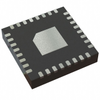
Microchip's ARM®-based SAM7S512 is a member of the SAM7S series of flash microcontrollers based on the 32-bit ARM7TDMI RISC processor. It operates at a maximum speed of 55MHz and features 512KB of dual bank flash memory and 64KB of SRAM.

The peripheral set includes a Full Speed USB device and PHY at 12Mbps, UART, two USARTs, TWI (I2C), SPI, SSC, two PWM timers, three 16-bit timers,RTT, 8x10-bit ADC and 32 IO lines.

It achieves single-cycle instruction access from embedded flash at 27 MIPS. The multi-layer bus matrix, multiple SRAM banks, PDC, and DMA support parallel tasks and maximize data throughput.

The SAM7S512 operates from 1.65V to 3.6V and is available in 64-pin LQFP and QFN packages.

Additional Features

    Microcontroller Features Core
    • ARM7TDMI® ARM® Thumb® Processor 32-bit RISC Architecture
    • High-density 16-bit Instruction Set
    • EmbeddedICE™ In-circuit Emulation, Debug Communication Channel Support
    Memories
    • 512 Kbytes (SAM7S512) Organized in Two Contiguous Banks of 1024 Pages of 256 Bytes (Dual Plane)
    • 64 Kbytes embedded SRAM, Single-cycle Access at Maximum Speed
    • Memory Controller (MC)
    • Memory Protection Unit
    System
    • Embedded 1.8V Regulator, Drawing up to 100 mA for the Core and External Components
    • Based on Power-on Reset Cells and Low-power Factory-calibrated Brownout Detector
    • Low-power RC Oscillator, 3 to 20 MHz On-chip Oscillator and One PLL
    • Power Management Controller (PMC)
    • Advanced Interrupt Controller (AIC)
    • Two-wire UART and Support for Debug Communication Channel interrupt, Programmable ICE Access Prevention
    • 20-bit Programmable Counter plus 12-bit Interval Counter
    • Windowed Watchdog (WDT)
    • Real-time Timer (RTT)
    • 32 Parallel Input/Output Controllers (PIO)
    • Eleven Peripheral DMA Controller (PDC) Channels
    • Four High-current Drive I/O lines, Up to 16 mA Each
    Package
    • 64-lead LQFP
    • 64-pad QFN
    Peripheral Features
    • One Synchronous Serial Controller (SSC)
    • Two Universal Synchronous/Asynchronous Receiver Transmitters (USART)
    • One Master/Slave Serial Peripheral Interfaces (SPI)
    • One USB 2.0 Full Speed (12 Mbits per second) Device Port
    • One Three-channel 16-bit Timer/Counter (TC)
    • One Four-channel 16-bit PWM Controller (PWMC)
    • One Two-wire Interface (TWI)
    Analog Features
    • One 8-channel 10-bit Analog-to-Digital Converter, Four Channels Multiplexed with Digital I/Os
    Fully Static Operation
    • Up to 55 MHz at 1.8V and 85⋅ C Worst Case Conditions
    • Up to 48 MHz at 1.65V and 85⋅ C Worst Case Conditions
    Debugger Development Support
    • SAM-BA - Interface with SAM-BA Graphic User Interface
    • IEEE® 1149.1 JTAG Boundary Scan on All Digital Pins

Supplier's Site Datasheet

Technical Specifications

  Microchip Technology, Inc.
Product Category Microcontrollers (MCU)
Product Number AT91SAM7S512
Clock Speed 55 MHz
Bits Other; 10-bit
Number 8
RAM 64 KB
ROM 512 KB
Unlock Full Specs
to access all available technical data

Similar Products

CC430F5137 16-Bit Ultra-Low-Power MCU, 32KB Flash, 4KB RAM, CC1101 Radio, AES-128, 12Bit ADC, USCI - CC430F5137IRGZ - Texas Instruments
Specs
Data Bus 16 Bit
Clock Speed 20 MHz
Features Watchdog Timer; DMA
View Details
3 suppliers
Microcontrollers - CG7380AM - Quarktwin Technology Ltd.
Infineon Technologies AG
Specs
Life Cycle Stage Removed; Obsolete
View Details
Microcontrollers - 7089864 - RS Components, Ltd.
RS Components, Ltd.
Specs
Data Bus 16 Bit; 32 Bit; 16 bit, 32bit
RAM 4 KB
ROM 32 KB
View Details
Embedded - Microcontrollers - ADUC842BCP8-5 - Lingto Electronic Limited
Specs
Data Bus 8 Bit; 8-Bit
View Details