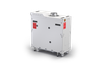
Pump Solutions Group WILDEN Pro-Flo Metal Pump P1

Description
The Pro-Flo™ patented air distribution system incorporates three moving parts: The unbalanced air valve spool, the pilot spool, and the main shaft/diaphragm assembly. The air valve spool location directs pressurized air to one air chamber while exhausting the other. The pressurized air chamber causes the main shaft/diaphragm assembly to move outward discharging liquid on that side and pulling liquid in on the other side. When the shaft reaches the end of its stroke, the opposite inner piston actuates the pilot spool. The pilot spool location either pressurizes or exhausts the large end of the unbalanced air valve spool. When the large end is pressurized, the piston is forced up so that the air supply is routed through the air valve spool to the right side of the pump. When the large end is exhausted, the piston is forced down so that the air supply is routed through the air valve spool to the left side of the pump. Note: This valve design incorporates an unbalanced spool with the smaller end of the spool pressurized continuously.
Description
The Pro-Flo™ patented air distribution system incorporates three moving parts: The unbalanced air valve spool, the pilot spool, and the main shaft/diaphragm assembly. The air valve spool location directs pressurized air to one air chamber while exhausting the other. The pressurized air chamber causes the main shaft/diaphragm assembly to move outward discharging liquid on that side and pulling liquid in on the other side. When the shaft reaches the end of its stroke, the opposite inner piston actuates the pilot spool. The pilot spool location either pressurizes or exhausts the large end of the unbalanced air valve spool. When the large end is pressurized, the piston is forced up so that the air supply is routed through the air valve spool to the right side of the pump. When the large end is exhausted, the piston is forced down so that the air supply is routed through the air valve spool to the left side of the pump. Note: This valve design incorporates an unbalanced spool with the smaller end of the spool pressurized continuously.

Suppliers

Company
Product
Description
Supplier Links
WILDEN Pro-Flo Metal Pump - P1 - Pump Solutions Group
Redlands, CA, USA
WILDEN Pro-Flo Metal Pump
P1
WILDEN Pro-Flo Metal Pump P1
The Pro-Flo™ patented air distribution system incorporates three moving parts: The unbalanced air valve spool, the pilot spool, and the main shaft/diaphragm assembly. The air valve spool location directs pressurized air to one air chamber while exhausting the other. The pressurized air chamber causes the main shaft/diaphragm assembly to move outward discharging liquid on that side and pulling liquid in on the other side. When the shaft reaches the end of its stroke, the opposite inner piston actuates the pilot spool. The pilot spool location either pressurizes or exhausts the large end of the unbalanced air valve spool. When the large end is pressurized, the piston is forced up so that the air supply is routed through the air valve spool to the right side of the pump. When the large end is exhausted, the piston is forced down so that the air supply is routed through the air valve spool to the left side of the pump. Note: This valve design incorporates an unbalanced spool with the smaller end of the spool pressurized continuously.

The Pro-Flo™ patented air distribution system incorporates three moving parts: The unbalanced air valve spool, the pilot spool, and the main shaft/diaphragm assembly. The air valve spool location directs pressurized air to one air chamber while exhausting the other. The pressurized air chamber causes the main shaft/diaphragm assembly to move outward discharging liquid on that side and pulling liquid in on the other side. When the shaft reaches the end of its stroke, the opposite inner piston actuates the pilot spool. The pilot spool location either pressurizes or exhausts the large end of the unbalanced air valve spool. When the large end is pressurized, the piston is forced up so that the air supply is routed through the air valve spool to the right side of the pump. When the large end is exhausted, the piston is forced down so that the air supply is routed through the air valve spool to the left side of the pump. Note: This valve design incorporates an unbalanced spool with the smaller end of the spool pressurized continuously.

Supplier's Site

Technical Specifications

  Pump Solutions Group
Product Category Vacuum Pumps and Vacuum Generators
Product Number P1
Product Name WILDEN Pro-Flo Metal Pump
Unlock Full Specs
to access all available technical data

Similar Products

Dry-Running Rotary Vane Vacuum Pumps - Seco SV 1008 C - Busch Vacuum Solutions
Specs
Vacuum Pump Type Mechanical
Configuration Individual Vacuum Pump
Application Industrial; Manufacturing; Packaging
View Details
Canned Drive Motor Positive Displacement Vacuum Blowers - Series HM - Aerzen USA Corp.
Specs
Vacuum Pump Type Mechanical
Configuration Individual Vacuum Pump
Application Industrial
View Details
Dry vacuum pumps (Screw type) SHINKO SEIKI - SST150 - Daitron Co., Ltd.
Specs
Vacuum Pump Type Mechanical
Configuration Individual Vacuum Pump
Application Industrial; Chemical; Industrial furnace; Resin forming; Chemical production, food-process & medical devices manufacturing; Silicon monocrystalline pulling; Vacuum cleaning
View Details
Lifetime™ LTP85 Silica Vacuum -  - Durovac Industrial Vacuums
Durovac Industrial Vacuums
Specs
Configuration Vacuum Pump System or Station
Application Industrial; Chemical; Manufacturing; Agriculture, Chemical, Metal Dust, Underground Mining, Industrial Construction
Pumping Speed 380 CFM (646 m³/hr)
View Details