ACCES I/O Products, Inc. ISA Bus Digital Input/Output Card IOD-72

Description
Features 72 channels of TTL digital I/O lines All I/O lines buffered by tristate transceivers. Outputs sink 24mA and source 15mA Four- and eight-bit groups independently selectable for I/O Pull-up resistors to provide CMOS and contact closure compatibility Cable crosstalk suppression by grounds on all even-numbered conductors 50-pin connector for compatibility with Western Reserve Controls, Opto-22, Gordos, Potter and Brumfield, etc. External interrupts These are 24-, 72-, and 120-bit half-size, 3/4-size, and full-size cards respectively. A Programmable Peripheral Interface chip, type 8255-5 provides three 8-bit ports (A, B, and C) for each 24-bit group. Each port can be independently programmed for either input or output. Port C can also be configured as two 4-bit ports. These cards fully implement Mode 0 of the 8255 PPI chip. (Consult the factory if you desire to operate in Mode 1.) Type LS245 bi-directional transceivers sink 24 mA (optionally 64 mA) and source 15 mA. These transceiver buffers provide hysteresis correction on inputs and added drive capability on outputs. The direction of the transceivers is set by software. Input/Output connections to IOD-24 are via a 50-pin connector on the mounting bracket. I/O connections to IOD-72 and IOD-120 are via 50-wire interface cables that extend through rectangular cut-outs in the mounting bracket and plug into headers on the card. Strain relief is provided for these cables. Ready-made displacement type ribbon cables are available from ACCES as p/n CAB50F-xx. (See the Accessories section of this catalog.) Alternate wires are connected to ground to provide shielding and minimize crosstalk. On models IOD-72 and IOD-120, you can enable/disable the I/O buffers under program control. If this is needed in a 24-bit application, a de-populated version of IOD-72 is available at reduced cost. Also, if only 96-bit operation is needed, there is a jumper on the IOD-120 to set that mode of operation. At each 24- bit port, two of the I/O lines can be used for User Interrupts; one line to enable/disable this function and one for the external interrupt signal. Interrupt levels 2-7 are selected by jumper on IOD-24. Interrupt levels 2-7, 10-12, 14, and 15 can be jumper selected on IOD-72 and IOD-120. Card I/O bus address selection is by DIP switches on the cards. The address can be anywhere in I/O space. On power-up or reset, all ports are automatically configured as inputs. This prevents spurious outputs. Before use, of course, the PPI should be software configured by writing to its control register. The table on the previous page defines bit assignments at each PPI.
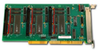
Description
Features 72 channels of TTL digital I/O lines All I/O lines buffered by tristate transceivers. Outputs sink 24mA and source 15mA Four- and eight-bit groups independently selectable for I/O Pull-up resistors to provide CMOS and contact closure compatibility Cable crosstalk suppression by grounds on all even-numbered conductors 50-pin connector for compatibility with Western Reserve Controls, Opto-22, Gordos, Potter and Brumfield, etc. External interrupts These are 24-, 72-, and 120-bit half-size, 3/4-size, and full-size cards respectively. A Programmable Peripheral Interface chip, type 8255-5 provides three 8-bit ports (A, B, and C) for each 24-bit group. Each port can be independently programmed for either input or output. Port C can also be configured as two 4-bit ports. These cards fully implement Mode 0 of the 8255 PPI chip. (Consult the factory if you desire to operate in Mode 1.) Type LS245 bi-directional transceivers sink 24 mA (optionally 64 mA) and source 15 mA. These transceiver buffers provide hysteresis correction on inputs and added drive capability on outputs. The direction of the transceivers is set by software. Input/Output connections to IOD-24 are via a 50-pin connector on the mounting bracket. I/O connections to IOD-72 and IOD-120 are via 50-wire interface cables that extend through rectangular cut-outs in the mounting bracket and plug into headers on the card. Strain relief is provided for these cables. Ready-made displacement type ribbon cables are available from ACCES as p/n CAB50F-xx. (See the Accessories section of this catalog.) Alternate wires are connected to ground to provide shielding and minimize crosstalk. On models IOD-72 and IOD-120, you can enable/disable the I/O buffers under program control. If this is needed in a 24-bit application, a de-populated version of IOD-72 is available at reduced cost. Also, if only 96-bit operation is needed, there is a jumper on the IOD-120 to set that mode of operation. At each 24- bit port, two of the I/O lines can be used for User Interrupts; one line to enable/disable this function and one for the external interrupt signal. Interrupt levels 2-7 are selected by jumper on IOD-24. Interrupt levels 2-7, 10-12, 14, and 15 can be jumper selected on IOD-72 and IOD-120. Card I/O bus address selection is by DIP switches on the cards. The address can be anywhere in I/O space. On power-up or reset, all ports are automatically configured as inputs. This prevents spurious outputs. Before use, of course, the PPI should be software configured by writing to its control register. The table on the previous page defines bit assignments at each PPI.

Suppliers

Company
Product
Description
Supplier Links
ISA Bus Digital Input/Output Card - IOD-72 - ACCES I/O Products, Inc.
San Diego, CA, USA
ISA Bus Digital Input/Output Card
IOD-72
ISA Bus Digital Input/Output Card IOD-72
Features 72 channels of TTL digital I/O lines All I/O lines buffered by tristate transceivers. Outputs sink 24mA and source 15mA Four- and eight-bit groups independently selectable for I/O Pull-up resistors to provide CMOS and contact closure compatibility Cable crosstalk suppression by grounds on all even-numbered conductors 50-pin connector for compatibility with Western Reserve Controls, Opto-22, Gordos, Potter and Brumfield, etc. External interrupts These are 24-, 72-, and 120-bit half-size, 3/4-size, and full-size cards respectively. A Programmable Peripheral Interface chip, type 8255-5 provides three 8-bit ports (A, B, and C) for each 24-bit group. Each port can be independently programmed for either input or output. Port C can also be configured as two 4-bit ports. These cards fully implement Mode 0 of the 8255 PPI chip. (Consult the factory if you desire to operate in Mode 1.) Type LS245 bi-directional transceivers sink 24 mA (optionally 64 mA) and source 15 mA. These transceiver buffers provide hysteresis correction on inputs and added drive capability on outputs. The direction of the transceivers is set by software. Input/Output connections to IOD-24 are via a 50-pin connector on the mounting bracket. I/O connections to IOD-72 and IOD-120 are via 50-wire interface cables that extend through rectangular cut-outs in the mounting bracket and plug into headers on the card. Strain relief is provided for these cables. Ready-made displacement type ribbon cables are available from ACCES as p/n CAB50F-xx. (See the Accessories section of this catalog.) Alternate wires are connected to ground to provide shielding and minimize crosstalk. On models IOD-72 and IOD-120, you can enable/disable the I/O buffers under program control. If this is needed in a 24-bit application, a de-populated version of IOD-72 is available at reduced cost. Also, if only 96-bit operation is needed, there is a jumper on the IOD-120 to set that mode of operation. At each 24- bit port, two of the I/O lines can be used for User Interrupts; one line to enable/disable this function and one for the external interrupt signal. Interrupt levels 2-7 are selected by jumper on IOD-24. Interrupt levels 2-7, 10-12, 14, and 15 can be jumper selected on IOD-72 and IOD-120. Card I/O bus address selection is by DIP switches on the cards. The address can be anywhere in I/O space. On power-up or reset, all ports are automatically configured as inputs. This prevents spurious outputs. Before use, of course, the PPI should be software configured by writing to its control register. The table on the previous page defines bit assignments at each PPI.

Features

  • 72 channels of TTL digital I/O lines
  • All I/O lines buffered by tristate transceivers. Outputs sink 24mA and source 15mA
  • Four- and eight-bit groups independently selectable for I/O
  • Pull-up resistors to provide CMOS and contact closure compatibility
  • Cable crosstalk suppression by grounds on all even-numbered conductors
  • 50-pin connector for compatibility with Western Reserve Controls, Opto-22, Gordos, Potter and Brumfield, etc.
  • External interrupts

These are 24-, 72-, and 120-bit half-size, 3/4-size, and full-size cards respectively. A Programmable Peripheral Interface chip, type 8255-5 provides three 8-bit ports (A, B, and C) for each 24-bit group. Each port can be independently programmed for either input or output. Port C can also be configured as two 4-bit ports. These cards fully implement Mode 0 of the 8255 PPI chip. (Consult the factory if you desire to operate in Mode 1.) Type LS245 bi-directional transceivers sink 24 mA (optionally 64 mA) and source 15 mA. These transceiver buffers provide hysteresis correction on inputs and added drive capability on outputs. The direction of the transceivers is set by software.

Input/Output connections to IOD-24 are via a 50-pin connector on the mounting bracket. I/O connections to IOD-72 and IOD-120 are via 50-wire interface cables that extend through rectangular cut-outs in the mounting bracket and plug into headers on the card. Strain relief is provided for these cables. Ready-made displacement type ribbon cables are available from ACCES as p/n CAB50F-xx. (See the Accessories section of this catalog.) Alternate wires are connected to ground to provide shielding and minimize crosstalk.

On models IOD-72 and IOD-120, you can enable/disable the I/O buffers under program control. If this is needed in a 24-bit application, a de-populated version of IOD-72 is available at reduced cost. Also, if only 96-bit operation is needed, there is a jumper on the IOD-120 to set that mode of operation. At each 24- bit port, two of the I/O lines can be used for User Interrupts; one line to enable/disable this function and one for the external interrupt signal. Interrupt levels 2-7 are selected by jumper on IOD-24. Interrupt levels 2-7, 10-12, 14, and 15 can be jumper selected on IOD-72 and IOD-120.

Card I/O bus address selection is by DIP switches on the cards. The address can be anywhere in I/O space. On power-up or reset, all ports are automatically configured as inputs. This prevents spurious outputs. Before use, of course, the PPI should be software configured by writing to its control register. The table on the previous page defines bit assignments at each PPI.

Supplier's Site

Technical Specifications

  ACCES I/O Products, Inc.
Product Category Data Acquisition
Product Number IOD-72
Product Name ISA Bus Digital Input/Output Card
Data Acquisition Data Acquisition Card; Input/Output Module
Form Factor PC Board
Outputs Analog Voltage Output
User Interface Computer Programmable
Host Connection Direct Backplane Interface
Unlock Full Specs
to access all available technical data

Similar Products

Safety IO Modules - 5003458 - RS Components, Ltd.
RS Components, Ltd.
Specs
Data Acquisition Output Module; Input/Output Module
Form Factor DIN Rail; Din rail
Agency Approval RoHS Compliant
View Details
G-Logger™ Data Acquistion System - SDI 3330 - Silicon Designs, Inc.
Specs
Data Acquisition DAQ Instrument; Datalogger
Form Factor USB-Powered Portable
User Interface Computer Programmable
View Details
Noncontact Position/Displacement Sensor - KD-2306 - Kaman Measuring & Memory LLC dba KMM Precision Measuring
Kaman Measuring & Memory LLC dba KMM Precision Measuring
Specs
Data Acquisition DAQ Instrument; Input/Output Module
Form Factor DIN Rail
Outputs Analog Voltage Output; Analog Current Output; Frequency or Pulse Output
View Details
Three Phase Power Data Logger - PCE-830-2 - PCE Instruments / PCE Americas Inc.
PCE Instruments / PCE Americas Inc.
Specs
Data Acquisition Datalogger
Form Factor Stand-alone
User Interface Front Panel
View Details