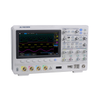
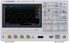
The 2567 is a 200 MHz, 4 Channel digital oscilloscope from BK Precision. Measure voltage or current signals over time in an electronic circuit or component to display amplitude, frequency and rise times, etc. Applications include troubleshooting, production test, and design.
Additional Features:
Bandwidth: 200 MHz
4 Channels
16 digital channels with logic analyzer (MSO upgrade)
Serial bus decoding supporting I²C, SPI,
UART/RS232, CAN, and LIN protocols (Decode upgrade)
25 MHz Function and Arbitrary Waveform Generator (AWG upgrade)
Large 8” widescreen display with 256-level color gradient
140,000 wfms/s waveform capture rate
Compact footprint and lightweight
High speed hardware-based pass/fail testing function and masking
Segmented acquisition history waveform record function (record length up to 80,000 frames)
Trigger types: Edge, Slope, Pulse, Video,
Window, Runt, Interval, Dropout, Pattern, Serial
FFT including seven other math functions:
Addition, Subtraction, Multiplication, Division, Integration, Differential, and Square Root
36 automatic measurements supporting statistics, gating, math, history and reference measurements
Multi-language user interface and built-in context sensitive help
Software provided for remote PC control
Front panel USB port for saving and recalling waveforms, setups, and screenshots
Standard LAN and USBTMC-compliant USB device port
Selectable 50 ω and 1 Mω input coupling
Three-Year Warranty
Specifications
Note: All specifications apply to the unit after a temperature stabilization time of 30 minutes over an ambient temperature range of 23 °C ± 5 °C.
Performance Characteristics
Bandwidth: 200 MHz
Typical Rise Time: < 1.8 ns
Sample Rate: 2 GSa/s (single channel), 1 MSa/s (dual channel)
Input Channels: 4 Analog Channels
Digital: 16 (-MSO models or with LA2560 upgrade)
Memory Depth: 140 Mpts (single channel), 70 Mpts (dual channel)
Waveform Update Rate: 140,000 wfms/s
Hardware Bandwidth Limits: 20 MHz
Input Coupling: DC, AC, GND
Input Impedance: 1 Mω ± 2% || (22 pF ±3 pF) 50 ω ± 2%
Ch to Ch Isolation: DC - Max BW > 35 dB
Acquisition System
Peak Detect: > 1 ns
Average: 4, 16, 32, 64, 128, 256, 512, 1024
Enhanced Resolution (Eres): 0.5, 1, 1.5, 2, 2.5, 3 bits selectable
Interpolation: Sin(x)/x, Linear
Vertical System
Vertical Resolution: 8 bits
Vertical Sensitivity: 500 μV/div to 10 V/div (1-2-5 )
Maximum Input Voltage: 1 Mω: < 400 Vpk; 50 ω: < 5 Vrms
DC Gain Accuracy: ±3%: 5 mV/div to 10 V/div; ±4%: < 2 mV/div
Horizontal System
Time Base Range: 2.0 ns/div to 50 s/div
Time Base Accuracy: ±25 ppm
Ch to Ch Deskew Range: <100 ps
Trigger System
Modes: Auto, Normal, Single
Coupling DC, AC, LF Reject, HF Reject, Noise Reject Ch1-Ch4
Trigger Level: Internal: ±4.5 div from center; External: EXT: ±0.6 V; EXT/5: ±3 V
Hold-Off Range: 100 ns to 1.5 s
Types: Edge, Slope, Pulse, Video, Window, Interval, Dropout, Runt, Pattern
Serial Trigger: I²C, SPI, UART/RS232, CAN, LIN
Cursors
Mode: Manual, Track
Measurements: δT, 1/δT, X2, X1, δV, Y2, Y1
Waveform Math
Math Operation: Add, Subtract, Multiply, Divide, FFT, Derivative, Integral, Square Root
FFT: Windows: Rectangle, Blackman, Hanning, Hamming, Flattop
Waveform Measurements
Voltage: Vpp, Vmax, Vmin, Vamp, Vtop, Vbase, Mean, Cmean, Stdev, Cstd, Vrms, Crms, FOV, FPRE, ROV, RPRE, Level@Trigger
Time: +SR, -SR, Period, Freq, +Width, -Width, Rise, Fall, BWidth, +Duty, -Duty, Time@Mid
Delay: Phase, FRR, FRF, FFR, FFF, LRR, LRF, LFF, Skew
Statistics: Current, Mean, Min, Max, Stdev, Count
Gating: Time domain
I/O Interface
Standard: USB Host, USB Device, LAN, Pass/Fail, Trigger Out
Pass/Fail: 3.3 V TTL Output
Display System
Display: 8” Color TFT-LCD, 800 x 480 Resolution
Wave Display Mode: Vectors, Dots
Persistence: Off, Infinite, 1 sec, 5 sec, 10 sec, 30 sec
Intensity Grading: 256 Levels
Language: English, French, Japanese, Korean, German, Russian, Italian, Portuguese, Simplified Chinese, Traditional Chinese
Environmental and Safety
Temperature: Operating: 10 °C to +40 °C
Storage: -20 °C to +60 °C
Humidity Operating: 85% RH, 40 °C, 24 hours
Storage: 85% RH, 65 °C, 24 hours
Altitude Operating: 3,000 m
Storage: 15,266 m
General
Power Requirements: 100 to 240 VAC, CAT II, 50 VA Max, 45 Hz to 440 Hz
Dimensions: (W x H x D) 13.8” x 5” x 8.8” (352 x 128 x 224 mm)
Weight: (4-ch) 7.9 lbs (3.6 kg); (2-ch) 7.5 lbs (3.4 kg)
Included Accessories: Passive probes (one per channel), power cord, certificate of calibration, USB (Type A to B) communication cable
Optional Accessories: 16-channel digital logic probe (LP2560) Trigger System
Edge Trigger
Slope: Rising, Falling, Rising & Falling
Source: CH1 to CH4/EXT/(EXT/5)/AC Line
Slope Trigger
Slope: Rising, Falling
Limit Range: <, >, < >, > <
Time Range: 2 ns to 4.2 s
Resolution: 1 ns
Pulse Width Trigger
Polarity: +wid, -wid
Limit Range: <, >, < >, > <
Pulse Width Range: 2 ns to 4.2 s
Resolution: 1 ns
Video Trigger
Signal Standard: NTSC, PAL, 720p/50, 720p/60, 1080p/50, 1080p/60, 1080i/50, 1080i/60, Custom
Sync: Any, Select
Trigger Condition: Line, Field
Window Trigger
Window Type: Absolute, Relative
Interval Trigger
Slope: Rising, Falling
Limit Range: <, >, < >, > <
Time Range: 2 ns to 4.2 s
Resolution: 1 ns
Dropout Trigger
Timeout: Type Edge, State
Slope: Rising, Falling
Time Range: 2 ns to 4.2 s
Resolution: 1 ns
Runt Trigger
Polarity: +wid, -wid
Limit Range: <, >, < >, > <
Time Range: 2 ns to 4.2 s
Resolution: 1 ns
Pattern Trigger
Pattern Setting: Invalid, Low, High
Logic: AND, OR, NAND, NOR
Limit Range: <, >, < >, > <
Time Range: 2 ns to 4.2 s
Resolution: 1 ns Serial Trigger
I²C Trigger
Condition: Start, Stop, Restart, No Ack, EEPROM, Address & Data, Data Length
Source (SDA/SCL): CH1 to CH4
Data format: Binary, Decimal, Hex, ASCII
Limit Range: EEPROM: =, >, <
Data Length: EEPROM: 1 byte; Address & Data: 1 to 2byte; Data Length: 1 to 12byte
SPI Trigger
Condition: Data
Source (CS/CLK/Data): CH1 to CH4
Data format: Binary, Decimal, Hex, ASCII
Data Length: 4 to 96 bit
Bit Value: 0, 1, X
Bit Order: LSB, MSB
UART/RS232 Trigger
Condition: Start, Stop, Data, Parity Error
Source (RX/TX): CH1 to CH4
Data format: Binary, Decimal, Hex, ASCII
Limit Range: =, >, <
Data Length: 1 byte
Data Width: 5 bit, 6 bit, 7 bit, 8 bit
Parity Check: None, Odd, Even
Stop Bit: 1 bit, 1.5 bit, 2 bit
Idle Level: High, Low
Baud Rate (Selectable): 600/1200/2400/4800/9
600/19200/38400/5760
0/115200 bit/s
Baud Rate (Custom): 300 bit/s to 334000 bit/s
CAN Trigger
Type: All, Remote, ID, ID + Data, Error
Source: CH1 to CH4
ID: STD (11bit), EXT(29bit)
Data format: Binary, Decimal, Hex, ASCII
Data Length: 1 to 2 byte
Baud Rate (Selectable): 5k/10k/20k/50k/100k/
125k/250k/500k/800k/
1M bit/s
Baud Rate (Custom): 5 kbit/s to 1 Mbit/s
LIN Trigger
Type: Break, Frame ID, ID+Data, Error
Source: CH1 to CH4
ID: 1 byte
Data format: Binary, Decimal, Hex, ASCII
Data Length: 1 to 2 byte
Baud Rate (Selectable): 600/1200/2400/4800/9
600/19200 bit/s
Baud Rate (Custom): 300 bit/s to 20 kbit/s
Available Upgrades
16-channel digital logic probe (LP2560): Optional on DSO Models. Standard on MSO Models
Logic analyzer license (LA2560): Optional on DSO Models. Standard on MSO Models
Bus decode and analysis license (DC2560): Optional on DSO and MSO Models
25 MHz waveform generator license (FG2560): Optional on DSO and MSO Models
Option Specifications Function/Arbitrary Waveform Generator (FG2560)
Waveforms: Sine, Square, Ramp, Pulse, DC, Noise, Cardiac, Gaus Pulse, Exp Rise
Arbitrary: 4 Slots for Arbitrary Waveforms
Maximum Output Frequency: 25 MHz
Sample Rate: 125 MSa/s
Frequency Resolution: 1 μHz
Frequency Accuracy: ±50 ppm
Vertical Resolution: 14 bits
Amplitude Range: -1.5 to +1.5 V @ 50 ω; -3 to +3 V @ 1 Mω
Output Impedance: 50 ω ±2%
Protection: Short-Circuit Protection
Sine Characteristics
Frequency: 1 μHz to 25 MHz
Offset Accuracy (100 kHz): ± (0.3 dB x Offset Setting Value + 1 mVpp)
Amplitude flatness: ±0.3 dB (100 kHz, 5 Vpp)
Spurious (non harmonics): DC to 1 MHz: -60 dBc; 1 MHz to 5 MHz: -55 dBc; 5 MHz to 25 MHz: -50 dBc
Harmonic distortion: DC to 5 MHz: -50 dBc; 5 MHz to 25 MHz: -45 dBc
Square/Pulse Characteristics
Frequency: 1 μHz to 10 MHz
Duty Cycle: 20% to 80%
Rise/Fall Time: < 24 ns (10% to 90%)
Overshoot (1 kHz, 1 Vpp Typical): < 3%
Pulse Width: > 50 ns
Jitter: < 500 ps + 10 ppm
Ramp Characteristics
Frequency: 1 μHz to 300 kHz
Linearity (Typical): < 0.1% of Pk-Pk (Typical, 1 kHz, 1 Vpp, 100% Symmetry)
Symmetry: 0% to 100% (Adjustable)
DC Characteristics
Offset Range: ±1.5 V (50 ω); ±3 V (High-Z)
Accuracy: ± (|offset|*1%+3 mV)
Noise Characteristics
Bandwidth: > 25 MHz (-3 dB)
Arbitrary Wave Characteristics
Frequency: 1 μHz to 5 MHz
Wave Length: 16 kpts
Sample Rate: 125 MSa/s Serial Decoder (DC2560)
Threshold: -4.5 to 4.5 div
Recorded List: 1 to 7 Lines
I²C Decoder
Signal: SCL, SDA
Address: 7 bit, 10 bit
SPI Decoder
Signal: CLK, MISO, MOSI, CS
Edge Select: Rising, Falling
Idle Level: Low, High
Bit Order: MSB, LSB
UART/RS232 Decoder
Signal: RX, TX
Data Width: 5, 6, 7, 8 bit
Parity Check: None, Odd, Even
Stop Bit: 1, 1.5, 2 bit
Idle Level: Low, High
CAN Decoder
Signal: CAN_H, CAN_L
Source: CAN_H, CAN_L, CAN_H-CAN_L
LIN Decoder
Supported Specification: Ver1.3, Ver2.0 MSO Digital Channels (LA2560/LP2560)-MSO Option
Digital Channels: 16
Sample Rate: 500 MSa/s
Memory Depth: 14 Mpts/Ch
Maximum Input Voltage: ± 20 Vpeak
Threshold Accuracy: ± (3% of threshold setting + 150 mV)
Input Dynamic Range: ± 10 V
Minimum Input Voltage Swing: 800 mVpp
Input Impedance: 100 kω || 18 pF
Maximum Input Frequency: 60 MHz
Minimum Detectable Pulse Width: 8.3 ns
Ch to Ch Skew: ± (1 digital sample interval)
User Defined Threshold Range: ± 3 V in 10 mV steps
Threshold Selections: TTL, CMOS, LVCMOS3.3, LVCMOS2.5, Custom (-3 to +3 V)
Front Panel Features:
8-inch TFT-LCD display
8-inch high resolution TFT-LCD display lets you see more details in your signal.
Advanced triggering
Isolate the signal with advanced triggering including Edge, Slope, Pulse, Video, Window, Interval, DropOut, Runt, and Pattern trigger types.
Auto setup
Vertical, horizontal, and trigger controls are automatically adjusted for fast signal display.
Intuitive channel operation
All channels in the 2560 Series are clearly indicated by their own color, labeled on the input, knobs, and display
16-Channel Digital Ports
Connect a logic analyzer probe to access 16 digital channels enabled with MSO upgrade or try 30 times for free with each unit.
USB host port
Connect your USB flash drive to conveniently store and recall waveform data, setups, and screenshots.
Serial Decoding
Decode and analyze I²C, SPI, UART/RS232, CAN, and LIN protocols and display results in binary, decimal, hex, or ASCII in real-time. Enabled with decode upgrade or try 30 times for free with each unit.
Arbitrary Waveform Generator Output
The 25 MHz waveform generator is enabled with the generator upgrade or try 30 times for free with each unit.
The Tools You Need
Fast 140,000 wfms/s Waveform Capture Rate
The 140,000 wfms/s update rate in normal mode helps detect infrequent anomalies and glitches.
Record Length up to 140 Mpts
The hardware-based Zoom function used with the record lengths of 140 Mpts enables users to capture more of their signal and quickly zoom into the event of interest.
Waveform History and Recording
Quickly scroll through millions of points with History Mode’s playback functionality to find difficult to capture events. Eliminate unnecessary idle signals and dead-time by selectively capturing up to 80,000 segments.
Hardware Pass/Fail and Masking
The 2560 Series’ high speed hardware based pass/fail limit function can perform up to 140,000 pass/fail tests per second.
Enhanced Resolution Mode
Enhanced Resolution (Eres) mode minimizes signal noise to reveal hidden detail when the signal is difficult to trigger and averaging methods are confined.
PC Connectivity
PC software is provided (free download at www.bkprecision.com) for seamless integration between the oscilloscope and PC. Capture and transfer waveforms, screen images, setups and measurement results to a Windows PC via the USB device port on the back of the instrument. A USB host port on the front allows for quick and easy screen saving.
256-level intensity grading and color temperature display
Discover and visualize more details of your signal for better analysis of its behavior.
The 2567 Digital Storage Oscilloscope delivers advanced features and debug capabilities for a wide range of applications. With up to 200 MHz bandwidth in a 4-channel configuration, each model offers a maximum sample rate of 2 GSa/s, and a maximum memory depth of 140 Mpts. In addition, these oscilloscopes provide an 8” color display with 256 levels of color grading combined with a high waveform update rate up to 140,000 wfms/sec, which allows the instruments to capture infrequent glitches with excellent signal fidelity. The logic analyzer and decode software provides 16 additional digital channels and serial bus decoding for I²C, SPI, UART/RS232, CAN, and LIN protocols.
Maximize productivity using extensive features such as digital filtering, waveform recording, pass/fail limit testing, and automatic measurements. The optional 25 MHz function/arbitrary waveform generator (AWG) provides stimulus output of 4 arbitrary waveforms, sine, square, ramp, pulse, DC, noise, cardiac, Gaussian pulse, and exponential rise/fall waveforms to the device under test.
The 2560 Series oscilloscopes are ideal for applications in design, education, service, and repair. This instrument offers a comprehensive set of tools to capture signal anomalies, decode serial bus protocols, and help speed up debug and analysis. The MSO, AWG, and decoding functionalities are available for upgrade in the field with the purchase of a license key.
The 2567 is a 200 MHz, 4 Channel digital oscilloscope from BK Precision. Measure voltage or current signals over time in an electronic circuit or component to display amplitude, frequency and rise times, etc. Applications include troubleshooting, production test, and design.
Additional Features:
- Bandwidth: 200 MHz
- 4 Channels
- 16 digital channels with logic analyzer (MSO upgrade)
- Serial bus decoding supporting I²C, SPI,
- UART/RS232, CAN, and LIN protocols (Decode upgrade)
- 25 MHz Function and Arbitrary Waveform Generator (AWG upgrade)
- Large 8” widescreen display with 256-level color gradient
- 140,000 wfms/s waveform capture rate
- Compact footprint and lightweight
- High speed hardware-based pass/fail testing function and masking
- Segmented acquisition history waveform record function (record length up to 80,000 frames)
- Trigger types: Edge, Slope, Pulse, Video,
- Window, Runt, Interval, Dropout, Pattern, Serial
- FFT including seven other math functions:
- Addition, Subtraction, Multiplication, Division, Integration, Differential, and Square Root
- 36 automatic measurements supporting statistics, gating, math, history and reference measurements
- Multi-language user interface and built-in context sensitive help
- Software provided for remote PC control
- Front panel USB port for saving and recalling waveforms, setups, and screenshots
- Standard LAN and USBTMC-compliant USB device port
- Selectable 50 Ω and 1 MΩ input coupling
- Three-Year Warranty
Specifications
Note: All specifications apply to the unit after a temperature stabilization time of 30 minutes over an ambient temperature range of 23 °C ± 5 °C.
Performance Characteristics
- Bandwidth: 200 MHz
- Typical Rise Time: < 1.8 ns
- Sample Rate: 2 GSa/s (single channel), 1 MSa/s (dual channel)
- Input Channels: 4 Analog Channels
- Digital: 16 (-MSO models or with LA2560 upgrade)
- Memory Depth: 140 Mpts (single channel), 70 Mpts (dual channel)
- Waveform Update Rate: 140,000 wfms/s
- Hardware Bandwidth Limits: 20 MHz
- Input Coupling: DC, AC, GND
- Input Impedance: 1 MΩ ± 2% || (22 pF ±3 pF) 50 Ω ± 2%
- Ch to Ch Isolation: DC - Max BW > 35 dB
Acquisition System
- Peak Detect: > 1 ns
- Average: 4, 16, 32, 64, 128, 256, 512, 1024
- Enhanced Resolution (Eres): 0.5, 1, 1.5, 2, 2.5, 3 bits selectable
- Interpolation: Sin(x)/x, Linear
Vertical System
- Vertical Resolution: 8 bits
- Vertical Sensitivity: 500 μV/div to 10 V/div (1-2-5 )
- Maximum Input Voltage: 1 MΩ: < 400 Vpk; 50 Ω: < 5 Vrms
- DC Gain Accuracy: ±3%: 5 mV/div to 10 V/div; ±4%: < 2 mV/div
Horizontal System
- Time Base Range: 2.0 ns/div to 50 s/div
- Time Base Accuracy: ±25 ppm
- Ch to Ch Deskew Range: <100 ps
Trigger System
- Modes: Auto, Normal, Single
- Coupling DC, AC, LF Reject, HF Reject, Noise Reject Ch1-Ch4
- Trigger Level: Internal: ±4.5 div from center; External: EXT: ±0.6 V; EXT/5: ±3 V
- Hold-Off Range: 100 ns to 1.5 s
- Types: Edge, Slope, Pulse, Video, Window, Interval, Dropout, Runt, Pattern
- Serial Trigger: I²C, SPI, UART/RS232, CAN, LIN
Cursors
- Mode: Manual, Track
- Measurements: ΔT, 1/ΔT, X2, X1, ΔV, Y2, Y1
Waveform Math
- Math Operation: Add, Subtract, Multiply, Divide, FFT, Derivative, Integral, Square Root
- FFT: Windows: Rectangle, Blackman, Hanning, Hamming, Flattop
Waveform Measurements
- Voltage: Vpp, Vmax, Vmin, Vamp, Vtop, Vbase, Mean, Cmean, Stdev, Cstd, Vrms, Crms, FOV, FPRE, ROV, RPRE, Level@Trigger
- Time: +SR, -SR, Period, Freq, +Width, -Width, Rise, Fall, BWidth, +Duty, -Duty, Time@Mid
- Delay: Phase, FRR, FRF, FFR, FFF, LRR, LRF, LFF, Skew
- Statistics: Current, Mean, Min, Max, Stdev, Count
- Gating: Time domain
I/O Interface
- Standard: USB Host, USB Device, LAN, Pass/Fail, Trigger Out
- Pass/Fail: 3.3 V TTL Output
Display System
- Display: 8” Color TFT-LCD, 800 x 480 Resolution
- Wave Display Mode: Vectors, Dots
- Persistence: Off, Infinite, 1 sec, 5 sec, 10 sec, 30 sec
- Intensity Grading: 256 Levels
- Language: English, French, Japanese, Korean, German, Russian, Italian, Portuguese, Simplified Chinese, Traditional Chinese
Environmental and Safety
- Temperature: Operating: 10 °C to +40 °C
- Storage: -20 °C to +60 °C
- Humidity Operating: 85% RH, 40 °C, 24 hours
- Storage: 85% RH, 65 °C, 24 hours
- Altitude Operating: 3,000 m
- Storage: 15,266 m
General
- Power Requirements: 100 to 240 VAC, CAT II, 50 VA Max, 45 Hz to 440 Hz
- Dimensions: (W x H x D) 13.8” x 5” x 8.8” (352 x 128 x 224 mm)
- Weight: (4-ch) 7.9 lbs (3.6 kg); (2-ch) 7.5 lbs (3.4 kg)
- Included Accessories: Passive probes (one per channel), power cord, certificate of calibration, USB (Type A to B) communication cable
- Optional Accessories: 16-channel digital logic probe (LP2560)
Trigger System
Edge Trigger
- Slope: Rising, Falling, Rising & Falling
- Source: CH1 to CH4/EXT/(EXT/5)/AC Line
Slope Trigger
- Slope: Rising, Falling
- Limit Range: <, >, < >, > <
- Time Range: 2 ns to 4.2 s
- Resolution: 1 ns
Pulse Width Trigger
- Polarity: +wid, -wid
- Limit Range: <, >, < >, > <
- Pulse Width Range: 2 ns to 4.2 s
- Resolution: 1 ns
Video Trigger
- Signal Standard: NTSC, PAL, 720p/50, 720p/60, 1080p/50, 1080p/60, 1080i/50, 1080i/60, Custom
- Sync: Any, Select
- Trigger Condition: Line, Field
Window Trigger
- Window Type: Absolute, Relative
Interval Trigger
- Slope: Rising, Falling
- Limit Range: <, >, < >, > <
- Time Range: 2 ns to 4.2 s
- Resolution: 1 ns
Dropout Trigger
- Timeout: Type Edge, State
- Slope: Rising, Falling
- Time Range: 2 ns to 4.2 s
- Resolution: 1 ns
Runt Trigger
- Polarity: +wid, -wid
- Limit Range: <, >, < >, > <
- Time Range: 2 ns to 4.2 s
- Resolution: 1 ns
Pattern Trigger
- Pattern Setting: Invalid, Low, High
- Logic: AND, OR, NAND, NOR
- Limit Range: <, >, < >, > <
- Time Range: 2 ns to 4.2 s
- Resolution: 1 ns
Serial Trigger
I²C Trigger
- Condition: Start, Stop, Restart, No Ack, EEPROM, Address & Data, Data Length
- Source (SDA/SCL): CH1 to CH4
- Data format: Binary, Decimal, Hex, ASCII
- Limit Range: EEPROM: =, >, <
- Data Length: EEPROM: 1 byte; Address & Data: 1 to 2byte; Data Length: 1 to 12byte
SPI Trigger
- Condition: Data
- Source (CS/CLK/Data): CH1 to CH4
- Data format: Binary, Decimal, Hex, ASCII
- Data Length: 4 to 96 bit
- Bit Value: 0, 1, X
- Bit Order: LSB, MSB
UART/RS232 Trigger
- Condition: Start, Stop, Data, Parity Error
- Source (RX/TX): CH1 to CH4
- Data format: Binary, Decimal, Hex, ASCII
- Limit Range: =, >, <
- Data Length: 1 byte
- Data Width: 5 bit, 6 bit, 7 bit, 8 bit
- Parity Check: None, Odd, Even
- Stop Bit: 1 bit, 1.5 bit, 2 bit
- Idle Level: High, Low
- Baud Rate (Selectable): 600/1200/2400/4800/9600/19200/38400/57600/115200 bit/s
- Baud Rate (Custom): 300 bit/s to 334000 bit/s
CAN Trigger
- Type: All, Remote, ID, ID + Data, Error
- Source: CH1 to CH4
- ID: STD (11bit), EXT(29bit)
- Data format: Binary, Decimal, Hex, ASCII
- Data Length: 1 to 2 byte
- Baud Rate (Selectable): 5k/10k/20k/50k/100k/125k/250k/500k/800k/1M bit/s
- Baud Rate (Custom): 5 kbit/s to 1 Mbit/s
LIN Trigger
- Type: Break, Frame ID, ID+Data, Error
- Source: CH1 to CH4
- ID: 1 byte
- Data format: Binary, Decimal, Hex, ASCII
- Data Length: 1 to 2 byte
- Baud Rate (Selectable): 600/1200/2400/4800/9600/19200 bit/s
- Baud Rate (Custom): 300 bit/s to 20 kbit/s
Available Upgrades
- 16-channel digital logic probe (LP2560): Optional on DSO Models. Standard on MSO Models
- Logic analyzer license (LA2560): Optional on DSO Models. Standard on MSO Models
- Bus decode and analysis license (DC2560): Optional on DSO and MSO Models
- 25 MHz waveform generator license (FG2560): Optional on DSO and MSO Models
Option Specifications
Function/Arbitrary Waveform Generator (FG2560)
- Waveforms: Sine, Square, Ramp, Pulse, DC, Noise, Cardiac, Gaus Pulse, Exp Rise
- Arbitrary: 4 Slots for Arbitrary Waveforms
- Maximum Output Frequency: 25 MHz
- Sample Rate: 125 MSa/s
- Frequency Resolution: 1 μHz
- Frequency Accuracy: ±50 ppm
- Vertical Resolution: 14 bits
- Amplitude Range: -1.5 to +1.5 V @ 50 Ω; -3 to +3 V @ 1 MΩ
- Output Impedance: 50 Ω ±2%
- Protection: Short-Circuit Protection
Sine Characteristics
- Frequency: 1 μHz to 25 MHz
- Offset Accuracy (100 kHz): ± (0.3 dB x Offset Setting Value + 1 mVpp)
- Amplitude flatness: ±0.3 dB (100 kHz, 5 Vpp)
- Spurious (non harmonics): DC to 1 MHz: -60 dBc; 1 MHz to 5 MHz: -55 dBc; 5 MHz to 25 MHz: -50 dBc
- Harmonic distortion: DC to 5 MHz: -50 dBc; 5 MHz to 25 MHz: -45 dBc
Square/Pulse Characteristics
- Frequency: 1 μHz to 10 MHz
- Duty Cycle: 20% to 80%
- Rise/Fall Time: < 24 ns (10% to 90%)
- Overshoot (1 kHz, 1 Vpp Typical): < 3%
- Pulse Width: > 50 ns
- Jitter: < 500 ps + 10 ppm
Ramp Characteristics
- Frequency: 1 μHz to 300 kHz
- Linearity (Typical): < 0.1% of Pk-Pk (Typical, 1 kHz, 1 Vpp, 100% Symmetry)
- Symmetry: 0% to 100% (Adjustable)
DC Characteristics
- Offset Range: ±1.5 V (50 Ω); ±3 V (High-Z)
- Accuracy: ± (|offset|*1%+3 mV)
Noise Characteristics
- Bandwidth: > 25 MHz (-3 dB)
Arbitrary Wave Characteristics
- Frequency: 1 μHz to 5 MHz
- Wave Length: 16 kpts
- Sample Rate: 125 MSa/s
Serial Decoder (DC2560)
- Threshold: -4.5 to 4.5 div
- Recorded List: 1 to 7 Lines
I²C Decoder
- Signal: SCL, SDA
- Address: 7 bit, 10 bit
SPI Decoder
- Signal: CLK, MISO, MOSI, CS
- Edge Select: Rising, Falling
- Idle Level: Low, High
- Bit Order: MSB, LSB
UART/RS232 Decoder
- Signal: RX, TX
- Data Width: 5, 6, 7, 8 bit
- Parity Check: None, Odd, Even
- Stop Bit: 1, 1.5, 2 bit
- Idle Level: Low, High
CAN Decoder
- Signal: CAN_H, CAN_L
- Source: CAN_H, CAN_L, CAN_H-CAN_L
LIN Decoder
- Supported Specification: Ver1.3, Ver2.0
MSO Digital Channels (LA2560/LP2560)-MSO Option
- Digital Channels: 16
- Sample Rate: 500 MSa/s
- Memory Depth: 14 Mpts/Ch
- Maximum Input Voltage: ± 20 Vpeak
- Threshold Accuracy: ± (3% of threshold setting + 150 mV)
- Input Dynamic Range: ± 10 V
- Minimum Input Voltage Swing: 800 mVpp
- Input Impedance: 100 kΩ || 18 pF
- Maximum Input Frequency: 60 MHz
- Minimum Detectable Pulse Width: 8.3 ns
- Ch to Ch Skew: ± (1 digital sample interval)
- User Defined Threshold Range: ± 3 V in 10 mV steps
- Threshold Selections: TTL, CMOS, LVCMOS3.3, LVCMOS2.5, Custom (-3 to +3 V)
Front Panel Features:
8-inch TFT-LCD display
8-inch high resolution TFT-LCD display lets you see more details in your signal.
Advanced triggering
Isolate the signal with advanced triggering including Edge, Slope, Pulse, Video, Window, Interval, DropOut, Runt, and Pattern trigger types.
Auto setup
Vertical, horizontal, and trigger controls are automatically adjusted for fast signal display.
Intuitive channel operation
All channels in the 2560 Series are clearly indicated by their own color, labeled on the input, knobs, and display
16-Channel Digital Ports
Connect a logic analyzer probe to access 16 digital channels enabled with MSO upgrade or try 30 times for free with each unit.
USB host port
Connect your USB flash drive to conveniently store and recall waveform data, setups, and screenshots.
Serial Decoding
Decode and analyze I²C, SPI, UART/RS232, CAN, and LIN protocols and display results in binary, decimal, hex, or ASCII in real-time. Enabled with decode upgrade or try 30 times for free with each unit.
Arbitrary Waveform Generator Output
The 25 MHz waveform generator is enabled with the generator upgrade or try 30 times for free with each unit.
The Tools You Need
Fast 140,000 wfms/s Waveform Capture Rate
The 140,000 wfms/s update rate in normal mode helps detect infrequent anomalies and glitches.
Record Length up to 140 Mpts
The hardware-based Zoom function used with the record lengths of 140 Mpts enables users to capture more of their signal and quickly zoom into the event of interest.
Waveform History and Recording
Quickly scroll through millions of points with History Mode’s playback functionality to find difficult to capture events. Eliminate unnecessary idle signals and dead-time by selectively capturing up to 80,000 segments.
Hardware Pass/Fail and Masking
The 2560 Series’ high speed hardware based pass/fail limit function can perform up to 140,000 pass/fail tests per second.
Enhanced Resolution Mode
Enhanced Resolution (Eres) mode minimizes signal noise to reveal hidden detail when the signal is difficult to trigger and averaging methods are confined.
PC Connectivity
PC software is provided (free download at www.bkprecision.com) for seamless integration between the oscilloscope and PC. Capture and transfer waveforms, screen images, setups and measurement results to a Windows PC via the USB device port on the back of the instrument. A USB host port on the front allows for quick and easy screen saving.
256-level intensity grading and color temperature display
Discover and visualize more details of your signal for better analysis of its behavior.
The 2567 Digital Storage Oscilloscope delivers advanced features and debug capabilities for a wide range of applications. With up to 200 MHz bandwidth in a 4-channel configuration, each model offers a maximum sample rate of 2 GSa/s, and a maximum memory depth of 140 Mpts. In addition, these oscilloscopes provide an 8” color display with 256 levels of color grading combined with a high waveform update rate up to 140,000 wfms/sec, which allows the instruments to capture infrequent glitches with excellent signal fidelity. The logic analyzer and decode software provides 16 additional digital channels and serial bus decoding for I²C, SPI, UART/RS232, CAN, and LIN protocols.
Maximize productivity using extensive features such as digital filtering, waveform recording, pass/fail limit testing, and automatic measurements. The optional 25 MHz function/arbitrary waveform generator (AWG) provides stimulus output of 4 arbitrary waveforms, sine, square, ramp, pulse, DC, noise, cardiac, Gaussian pulse, and exponential rise/fall waveforms to the device under test.
The 2560 Series oscilloscopes are ideal for applications in design, education, service, and repair. This instrument offers a comprehensive set of tools to capture signal anomalies, decode serial bus protocols, and help speed up debug and analysis. The MSO, AWG, and decoding functionalities are available for upgrade in the field with the purchase of a license key.